
When you hear the name Accurate Fishing being mentioned, what is the first thing that comes to your mind? Do you envision solidly built reels? Aircraft aluminium billets milled into reels? Twin drags? Titanium drag plates? CNC lathed parts? Strangely for me, a gaff comes to my mind first, and oh what a well made gaff that was indeed!
I’ve once upon a time thought Accurate was an aftermarket “tuning” house that made Accuframes for the real deal reels like Penns. Boy, what little did I know. But that Accurate gaff that I saw still stands today as the standard by which I judge gaffs. Funny how our values are all influenced by what we see and experience in our earlier days. So it was not until my friend Bernard shew me his silver reel in the 90s that I truly came to know Accurate reels as a serious contender in the game reel market despite the fact that their reels are not garbed in gold which was de rigueur for a game reel to be taken seriously in those days. But I digress…
So as usual, let’s begin by taking a look at this reel before I crack it open. In this Step-by-step, I’ll try to include the schematic key number of this reel with a “#”. But before you decide on cracking your Accurate reel open, you should spend some time at http://www.accuratefishing.com. There’s lots of helpful videos on maintenance etc to watch, so reading this step-by-step may actually be redundant.
External views of this reel

This reel is really tiny, other than the full sized handle. In fact its spool is smaller than Shimano’s Talica 8II.

It even has a cast control knob!
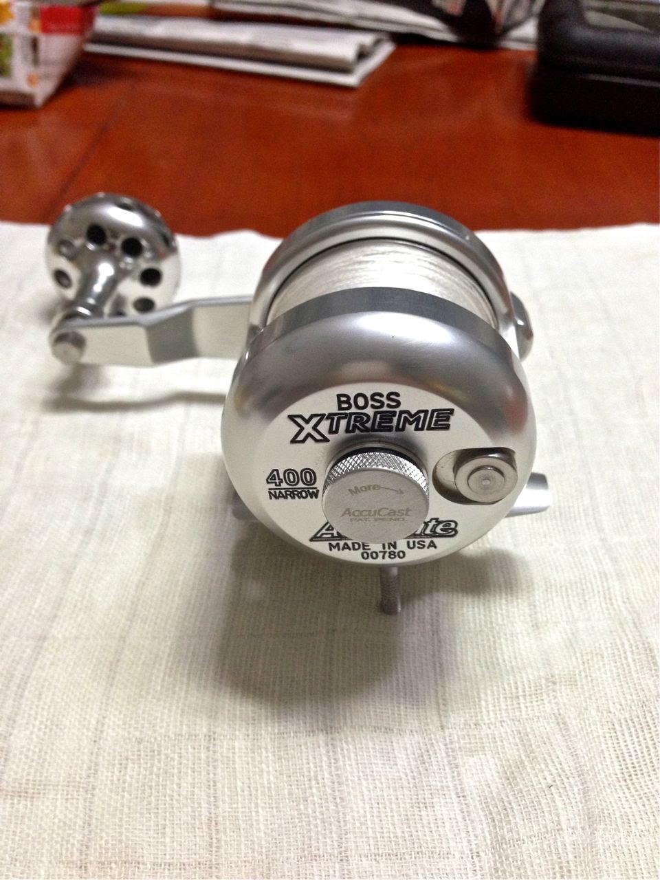
But it sure has a good heft despite its small size.


This reel has all metal parts except for that piece of plastic #20 Gear Cover which destroyed its design integrity. No doubt, plastic may be a lighter, better material to use but it’s the aesthetics that got jarred by the application. Perhaps metallised plastic may better address this?

Underside, the #71 Frame (Foot) is carved out of Aluminium stock, fastened by 4 Philips Head Stainless steel #72 Base Screws.

Schematics
Click this to get the Schematic for the bx.ipb
Always have the reel’s schematics with you when you strip down the reel. The link above is a schematic that can be used for the Boss 400 series, 500 series and 600 series.
Some tools and kit I used in working this reel
Before you embark on stripping the reel, check that you have the necessary tools to do the job. It can be really frustrating to be halfway through stripping a reel only to find that you are in want of a tool to complete the job. Then you go out to buy the tool and come home to find the dog had scattered your reel to the four corners of the room and now some part is lost… Now it’s hard to stay angry with the dog so instead of blaming yourself, be prepared. Get your tools and kit in order before embarking.
For those of us who use metric, this reel may be a challenge as the hex screws are SAE sizes. I know I did. Fortunately, I have a pair of adjustable spanner that’s very accurate to remove the #23 Shaft Handle Screw and #70 Frame Studs. I believe the bearings are not metric too, so I’ve included the vernier caliper pictures for you to decide which fraction of an inch it is.
You need a T-8 Torx wrench to remove the two #1 Handle Keeper Screws

T-6 sized Torx wrench needed for the four #24 Sideplate Screws.

T-15 Torx wrench to remove #88 Power Knob Top Screw

3/16th Allen Wrench to remove #106 Cast Control Frame Screw if it has been turned in beyond the #107 Cast Control Frame Knob’s ability to reach.

You also need a series of Philips Head screwdrivers from PH1 to PH3

You also need a pair of Circlip Pliers, a small Slot head screwdriver, Needle-nosed Forceps and some degreasing fluid like brake cleaner, acetone or lighter fuel.

For your safety, Do Not use lighter fuel if you are using electrical appliances like hairdryer, powered screwdriver or ultrasonic cleaner. Use Simple Green cleaner instead.
Cal’s Universal Grease is great stuff for gears and drag.

Quicksilver 2-4-C Marine Grease is used to delay the onslaught of galvanic corrosion and keep screws and bolts free from seizing. You can use any brand of marine grease, but test before using to ensure it doesn’t react with your other lubricants causing them to gum up or break down.

For best casting ability, I use TSI-301 lubricant. It dries to a very thin film allowing spool bearings to spin freely.

To remove the shields from Ball Bearing races, you need a very sharp hook. I use a Dai Ichi size 13 AJI hook. These are very sharp but the points do get bent (as in this picture) so always use new hooks when you find difficulty in removing the bearing shield retainers.

A light oil like CorrosionX for the anti-reverse bearings. (You can also use ReelX instead)

I usually don’t use Loctite. However I’d use a drop on the #88 Power Knob Top Screw to prevent this from working loose.

Some unique steps in stripping this reel
There’s some stuff on this reel that’s ingeniously hidden from view by the reel designers to give it that flawless exterior.
Here are some. Note that the following pictures are not necessarily in chronological order of dissembly.
To detach Spool sub assembly from the #2 Gear Side Plate Sub Assembly, use fingernails (or a thin screwdriver) to carefully pry out #33 Tension Cap Cover. This will expose #42 Spool Shaft Retainer. When that is detached, your spool sub assembly should be able to slide out easily. If it doesn’t, use a wooden dowel or chopstick as a drift and drive it against #41 Spool Shaft with a small hammer.

The rubber cap over #12 Power Knob is very snug. To avoid scratching the shiny knob, use a wooden dowel and push cap out from the edges as shown. Then you can access the Torx screw to undo the sub assembly.

#107 Cast Control Frame Knob is held in place by a delrin #108 Cast Control Frame Knob Clip. Locate the gap between the two legs of #108 Cast Control Frame Knob Clip and gently push apart with any fine tipped tool.

The #108 Cast Control Frame Knob Clip will then be able to be pulled out with a pair of forceps.

It’s Very Easy to strip this reel!
Four Torx screws and an E-clip are all it takes to break this reel into three sub assemblies. A good reel design in my opinion is one that not only makes a reel effective in use but is also is easy to do maintenance. And This reel is a good example of one.

Here are the sum of parts of this reel, when stripped down, waiting for a Simple Green bath. The only parts that I did not remove are the O-rings and #4 Anti-Reverse Bearing. I usually do not attempt to remove rubber O-rings unless I have a replacement spare in hand.

As I strip down the reel, I strip them by sub assemblies of the three groups in the above picture. I’d then lay the parts from left to right, in the order that they were removed, within their sub assemblies.
Pulling apart the spool and drags
Here the Spool and drags are stripped down. Both the #48 Titanium Washers can be further detached, but I see no need to be taking that further apart as there’s no servicing needed there.

The #41 Spool Shaft is 4.9mm Diameter. For those who want to sleeve the spool shaft bearings, the sleeve dimensions should be approximately 5mm ID x 7mmOD x 15mm ± long.

ID of the #34 Spool is 7.2mm

Both the #36 Spool Bearings are 12.7mm x 4.7mm x 5mm (OD x ID x Thickness). I believe this is not a metric size bearing, so I’m including pictures of the measurements here, for the interest of those who can calculate the fractional inch.


The shields on both these #36 spool bearings are not replaceable. Since owner wants his bearings to be shielded, I degreased them using Zippo lighter fluid and compressed air – a tedious process since the shields are in place. I then used TSI-301 – a dry lubricant, to re-lube them.

Re lubrication of bearings
#16 Gear Sideplate bearing have rubber shields. These are easy to pry out.

Use a sharp hook to pry out the rubber covered shields.

I’m a little surprised by the hidden inconsistencies in this reel. Here, you see the smaller #82 Tension Cam Bearing to be grease packed but the bigger #16 Gear Sideplate bearing is dry.

After degreasing the bearings and ensuring they are free spinning and dry, repack with a light grease. I lighten a tiny dab of Cal’s grease by mixing in a few drops of CorrosionX for this purpose.
If you are using different lubes, please test that your lubes will not react against each other before you attempt to mix lubes.
Handle bearings have shields held in place with a C clip
#81 Handle Large Bearing size is 11mm x 7mm x 3mm. #80 Handle Small Bearing size is 9mm x 5mm x 3mm (OD x ID x Thickness). They have removable shields held in place by a C clip.

To take shields apart, locate the very tiny gap (so do this with optical assistance and bright lighting) formed at the ends of the C clip. Pry one end out with a sharp hook. If you are unable to pry the end out, it means your hook is not sharp enough.
For Handle Knob bearings, I pack them with “Lightened” Cal’s Grease, after I had thoroughly degreased and dried them.

When refitting the shields, the concave side of the shield should face the balls and cage. C clip will press against the convex side.

Coarse finishing and some surprising disappointments
This reel had seen water only for a total of four days, two days each time, a month apart. The reel was rinsed with fresh water at the end of every day. When I stripped the reel, there’s a layer of grease over everything. So I’m surprised to see pitting here. Is it corrosion or are there bubbles in the aluminium billet? Also, the coarse, uneven milling marks could have been better honed away. This and those shown below make me wonder if QC of material have been really tight for a reel of such precision as an Accurate.

These three groups of scratches on #7 Main Gear are puzzling. Why are they there? Why spaced so perfectly?

Nicks and scratches on the spool flange – a sign of poor material handling?

Pits on #45 Clicker Drag Cap

Pitting on #21 Main Lever Arm.

I’m also surprised that Accurate chose to use such a tiny screw (T-6 Sized Torx) to hold the reel together. I voiced my concern with some fishing friends and one had already experienced the consequence!

Sideplate assembly begins
Before I reassemble any reel, I like to protect the metal surfaces with a coat of Marine grease so as to delay the onset of galvanic corrosion. I use a stiff bristled paintbrush to apply a coat of Quicksilver 2-4-C Marine grease for this purpose. You can use any other marine grease of your liking. What is important is to test your grease with all your other lubricants to check that mixing them does not result in any undesirable chemical reaction. If you are curious why I have so much faith in Marine grease ability to prevent corrosion, Read this

I coat everything liberally with Marine grease, but I took special care to avoid getting the grease into the #4 Anti Reverse Bearing.

You should use a light oil eg CorrosionX for this bearing. Never use grease as the thick viscosity of grease may cause this bearing to fail.
Also remember to cover the outside contact surfaces with Marine grease.

Coat contact surfaces of #21 Main Lever Arm with Marine Grease.

The rear surfaces of of #21 Main Lever Arm are showing signs of pitting. Marine grease can only delay the effects of Galvanic Corrosion, not totally prevent it.

The two notches on #25 Tension Cam Track should mate with two corresponding steps of #21 Main Lever Arm.

Seat #25 Tension Cam Track within of #21 Main Lever Arm and adjust to ensure the notches mate up squarely.

Give it a thick coat of Cal’s Universal Reel Grease.

Seat the Teflon #9 Main Lever Washer first.

Ensure that it sits flat at the bottom or you might have a hard time attaching your #29 Main Lever Retainer later.

Apply a layer of Cal’s Grease on #9 Main Lever Washer. Grease and snap on #5 Gear Shaft Bushing (Small)

Fill the hole on #21 Main Lever Arm with Marine Grease. Then insert the clicker spring in as far as it will go (This Spring and Clicker Stud is not shown in the schematic). The grease will help hold this spring in place when you re-assemble.

The black Delrin Clicker Stud is a tiny, fiddly thing. The domed side should be facing away from the spring.

Grease helps to hold the Clicker Stud temporarily in place. Since this is a fiddly operation, it is best to get an assistant to help you, and at the meanwhile, prepare yourself ahead for some of the subsequent steps.

Prepare your #29 Main Lever Retainer by attaching to Circlip pliers and then adjusting circlip till it is flush with the tips of the pliers – not like what you see here. Failing which, you will be fumbling around with the #21 Main Lever Arm while #29 Main Lever Retainer will be difficult to fit in.

Carefully reassemble #21 Main Lever Arm with the clicking stud to #3 Sideplate. Have your assistant use a piece of tape to hold down #21 Main Lever Arm as you’ll need both hands for the next operation.

Ensure that #21 Main Lever Arm is seated flat and a groove is clearly seen on the base of the hexagonal post. If it is not, you will have to remove the #21 Main Lever Arm, reseat the Teflon #9 Main Lever Washer flat against #3 Sideplate and repeat the fiddly exercise of reassembling #21 Main Lever Arm with that spring loaded black Delrin Stud which seem to have its own idea of where it wants to go, which is the opposite of your intentions.

Using your prepared circlip pliers, attach #29 Main Lever Retainer into the groove. Your assistant can help you use a screwdriver to push #29 Main Lever Retainer home.
Phew! The awkwardest manoeuver is over. You deserve a break. Go on and get your cuppa cha, and spew your vulgarities outside. I’ll wait for you here. I understand.
You’re back! Good… Let’s continue… Give your #21 Main Lever Arm a test for good fitting.

Slide it all the way to full and back to free. You should be able to feel each click indent and the #21 Main Lever Arm should be sliding smoothly without resistance.

Grease and insert #5 Gear Shaft Bushing

Press #5 Gear Shaft Bushing till it is flush with #3 Sideplate.

Grease the two #18 Strike Button Spring and seat within #17 Strike Button.

Seat #17 Strike Button into #3 Sideplate. Note that in this picture above, the #17 Strike Button is not seated correctly.

Also note that #17 Strike Button is kidney shaped and corresponds to a kidney shaped hole on #3 Sideplate. In the picture above, #17 Strike Button is installed incorrectly.

Correctly seated #17 Strike Button should peep through #3 Sideplate.

There are two sides of #19 Strike Button Cover.

The #18 Strike Button Springs are centered over the two nubs on #19 Strike Button Cover and the curve on it should match the curve of #3 Sideplate.

Grease the threads of #22 Strike Button Screws with a Marine Grease.

Fasten and repeat for the other side. Touch up the surfaces with Marine grease.

Install #16 Gear Sideplate Bearing.

Apply Cal’s Universal Grease to #27 Tension Cam and #30 Tension Cam Washer

Connect #27 Tension Cam and #30 Tension Cam Washer together. Note that this is reverse threaded i.e., to screw it in, you turn it by the unscrew direction.
Fit #27 Tension Cam and #30 Tension Cam Washer sub assembly into #21 Main Lever Arm, taking care to seat the two #28 Tension Cam Pins into their grooves on #25 Tension Cam Track.

Sorry about the distracting piece of lint.
Push #6 Gear Shaft through #7 Main Gear. Ensure that the square peg of #6 Gear Shaft (not shown in this picture) seats in the square hole of #7 Main Gear.

Apply Cal’s Universal Grease on #7 Main Gear, taking care to avoid contaminating #6 Gear Shaft with grease.

Seat #86 Main Gear Shaft Washer flat against #7 Main Gear.

Apply Cal’s Universal Grease to #86 Main Gear Shaft Washer.

Drop a few drops of CorrosionX oil and work it into the needle bearings of #4 Anti Reverse Bearing. If you don’t have ReelX or CorrosionX, you can use any light oil for this. Do Not use grease as it can cause the #4 Anti Reverse Bearing to slip.

Push #6 Gear Shaft through #4 Anti Reverse Bearing. Apply Cal’s Universal Grease to #7 Main Gear, working grease between the teeth.

Press #6 Gear Shaft all the way through taking care to note it is seated flush within the square hole of #7 Main Gear.

Hmmm, the groove on #6 Gear Shaft looks like a Circlip is missing here. However, there is none prescribed in the schematics and neither in the reel. So take care you do not push it out by accident when you continue with your assembly.

Grease the inside of #30 Tension Cam Washer.

Drop in #82 Tension Cam Bearing.

Put the #3 Sideplate sub assembly aside for now.
Frame Assembly
Butter up insides of #62 Frame with Marine Grease to delay corrosion. Observe the black pits that has already formed in the metal. If they are corrosion, the anodizing is suspect. If they are holes in the metal, the billet from which this frame is cut is suspect.

There are two sides of #63 Clicker Ring. This uneven side should face the spool.

There are two sides of #63 Clicker Ring. This flat side should be against the frame.

Catch #66 Clicker Dog between the legs of #63 Clicker Ring.

Place a small dab of Marine Grease on the two #68 Clicker Ring Screws and work the grease into the threads.

Secure #63 Clicker Ring with the two #68 Clicker Ring Screws.

Using 3/16th Hexagonal Wrench as a handle, apply Cal’s Universal Grease to threads of #106 Cast Control Frame Screw.

Grease the surrounding area and rubber #105 Frame O-Ring. Screw in #106 Cast Control Frame Screw till it sits flush with #62 Frame.

Grease the insides of #107 Cast Control Frame Knob with Marine Grease to delay corrosion damage.

Mate the Hexagonal shaft of #107 with Cast Control Frame Knob with #106 Cast Control Frame Screw.

Spread the jaws of #108 Cast Control Frame Knob Clip to clamp around groove in #107 Cast Control Frame Knob. Push till the jaws snap into the slots in #107 Cast Control Frame Knob.

#107 Cast Control Frame Knob is secured.

Work #65 Clicker Knob to ensure it can engage and disengage positively. If there is difficulty, check for proper seating of #63 Clicker Ring, or if it is cracked.

Insert #83 Frame Bearing.

Secure #83 Frame Bearing with #67 Frame Retainer.

Apply Marine Grease to #62 Frame and #71 Frame Base (Foot) to delay Corrosion damage.

Take care to also cover the countersunk holes on #71 Frame Base (Foot).

Fill threads of the four #72 Frame Base Screws with Marine Grease and secure #71 Frame Base (Foot) to #62 Frame.

Grease threads of #70 Frame Studs with Marine Grease and attach.

See the excess grease oozing out from the holes? I can afford to be careless with using too much grease here as there’s escape holes for them to squeeze out. However, don’t try doing this for the Torx screws on the frame. There’s no overflow holes there. And since grease doesn’t compress well, something will give eventually… your frame may crack from grease pressure.

Tighten firmly but take care not to overtorque.

Power Knob Assembly
Grease the insides of #12 Power Knob with Marine grease.

There’s an amber coloured transparent plastic washer that’s not in the schematics.

Place amber plastic washer into #12 Power Knob

Place #81 Handle Large Bearing into #12 Power Knob.

Protect #13 Handle Pin with Marine Grease.

Insert #13 Handle Pin through #12 Power Knob. Protect with Marine Grease.

Insert #80 Handle Small Bearing into #12 Power Knob.

Thread lock has been the bane of many reel owners when they find their screws are locked fast by excessive thread lock. However, this is where I make an exception. This #88 Power Knob Top Screw is short, and is not reverse threaded. It is possible for it to work loose. So I apply a small drop of Blue Loctite to ensure this screw stays fastened yet is able to be removed for future servicing.

Fasten #88 Power Knob Top Screw with T-15 Torx wrench.

Snap on Rubber Cap. Your Handle is done! It’s now time to give your bladder a break. Go ahead, I’ll wait for you. And down a cold beer for me too.

Spool and Drag Assembly
Degrease the insides of #34 Spool.

Slap on a coat of Cal’s Universal Grease.

Drop in #36 Spool Bearing.

Degrease #37 Fiber Washer and scuff up the weave with a toothbrush.

Sparingly paint on a coat of Cal’s Grease to #37 Fiber Washer.

Observe that #41 Spool Shaft has two dissimilar ends. The end with a longer flat is for the pinion side of the spool.

Check your line lay on the spool to determine which side is which. Insert #41 Spool Shaft. Slide in #49 Spool Spring to the longer side of the shaft.

Next, slide in #52 Pinion Bushing down the longer side of #41 Spool Shaft.

Slide on #47, #48 and #51 Pinion Gear Sub Assembly and grease with Cal’s Universal Grease.

Fix on #57 Spool Cover G/S and secure with four #39 Spool Cover Screws. Hand tighten with a small slotted screwdriver. DO NOT Overtighten.

Repeat procedure with the opposite side.

Slide in #45, #47, #48 Clicker Drag Cap Sub Assembly.

Coat with Cal’s Universal Grease.

Attach #38 Spool Cover C/S and secure with four #39 Spool Cover Screws. Hand tighten, taking care not to overtorque.

Slide on two pieces of #54 Spool Adj Washer. In the Schematic, there are three pieces of different sizes. This reel came with two and both have the same thickness.

Snap on #42 Spool Shaft Retainer to a groove on #41 Spool Shaft.

Final Assembly
Touch up the flanges on #3 Sideplate with Marine Grease that may have smudged off during assembly.

Snap on plastic #20 Gear Cover.

Work Cal’s Universal Grease into teeth of #51 Pinion Gear.

Attach Spool Sub Assembly to Sideplate Sub Assembly.

To access the groove on #41 Spool Shaft, push # 21 Main Lever Arm to free and loosen #30 Tension Cam Washer fully.

With #41 Spool Shaft on a stack of newspapers or some firm padding, push down on #3 Sideplate sub assembly to reveal the groove on #41 Spool Shaft.
Secure with #42 Spool Shaft Retainer.

Apply a dab of grease and snap shut with #33 Tension Cam Cover.

Clean away excess grease that may hinder spool free spin, but grease the flanges with Marine Grease.

Apply a small dab of grease to the four #24 Sideplate Screws and work grease evenly between the threads. Clean off any excess grease.

Mate #3 Sideplate assembly with #62 Frame.

Tighten the four #24 Sideplate Screws taking note not to over torque.

Apply a dab of Cal’s Universal Grease to the square peg end of #6 Gear Shaft.

Attach White Teflon #77 Handle Washer.

Grease Square hole on #79 Handle.

Mate #79 Handle with #6 Gear Shaft.

Grease #23 Gear Shaft Handle Screw.

Attach and tighten #23 Gear Shaft Handle Screw.

Apply a dab of Marine Grease to the two #1 Handle Keeper Screws.

Attach to #79 Handle. It may be necessary to adjust the #23 Gear Shaft Handle Screw in order for #1 Handle Keeper Screws to fit in.

Wet a rag with some Simple Green and wipe away excess grease from the outsides of the reel.
Your reel is serviced! Enjoy!.
HTH,
LL
PS: I was curious how much smoother the drag can be after greasing with Cal’s Drag Grease. So I hung it up and adjusted the drag to spill as little line as possible smoothly, while it hung on its own weight. The longer the reel takes to slide down by a metre, the smoother is the drag. I was shocked by the results as I thought the reel had not moved, until I saw the slow rotation of the spool!
I hope this step-by-step guide helped you in servicing your own reel too. If you found this useful, please click the blue LIKE and FOLLOW buttons. If you would like me to help you service your reel, or if you would like to help me with the cost of keeping this blog running, please drop me a message via WhatsApp at +65-9431-0400. Thank You!
© Lawrence Lee
All Rights Reserved

Great Post, done quite a few of these. As far as I’m aware the groove in the main drive shaft was for a very sml o ring. Very early models had a very sml dia o ring on the shaft, latter models did not as they didn’t work!! Capillary action sucks water past the bushing straight onto the bearing, a design fault with these reels.
Thanks for posting this.
You save my day
I’m Glad it helped you.
Pingback: Ball bearing shield removal | Gasping Gurami·